Page 1 of 1
1) For low-pass filter circuit of Fig.1 a) Find the transfer function(H(jo)) and cut-off frequency(fc) of the circuit wi
Posted: Tue May 24, 2022 9:32 am
by answerhappygod
- 1 For Low Pass Filter Circuit Of Fig 1 A Find The Transfer Function H Jo And Cut Off Frequency Fc Of The Circuit Wi 1 (102.3 KiB) Viewed 34 times
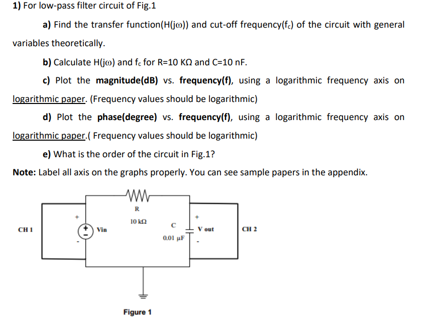
1) For low-pass filter circuit of Fig.1 a) Find the transfer function(H(jo)) and cut-off frequency(fc) of the circuit with general variables theoretically. b) Calculate H(jo) and fc for R=10 KQ and C=10 nF. c) Plot the magnitude(dB) vs. frequency(f), using a logarithmic frequency axis on logarithmic paper. (Frequency values should be logarithmic) d) Plot the phase(degree) vs. frequency(f), using a logarithmic frequency axis on logarithmic paper. ( Frequency values should be logarithmic) e) What is the order of the circuit in Fig.1? Note: Label all axis on the graphs properly. You can see sample papers in the appendix. R 10 ΚΩ CH 1 Vin V out CH 2 0.01 μF Figure 1