Page 1 of 1
The signal from the tank is buffered and fed to a microcontroller using the filter circuit shown in Fig. Q4b, where V₁ i
Posted: Tue May 24, 2022 8:56 am
by answerhappygod
- The Signal From The Tank Is Buffered And Fed To A Microcontroller Using The Filter Circuit Shown In Fig Q4b Where V I 1 (63.48 KiB) Viewed 34 times
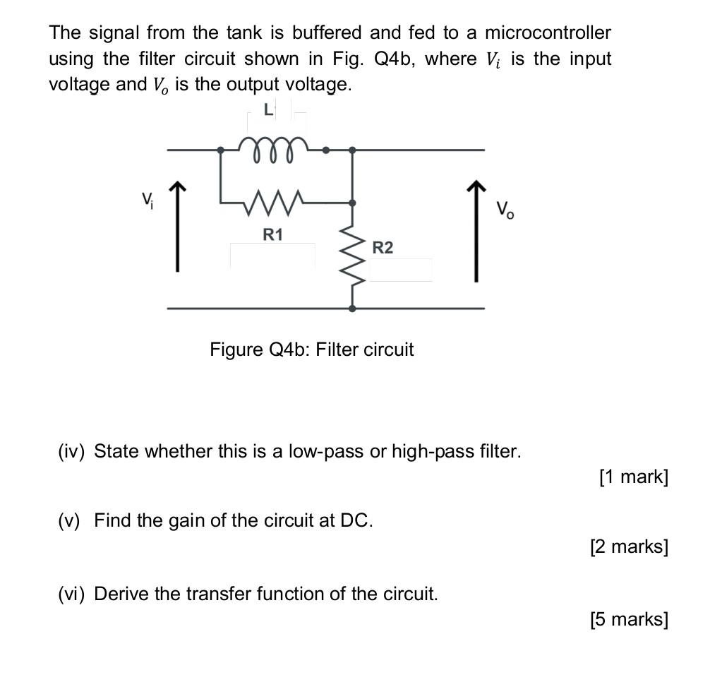
The signal from the tank is buffered and fed to a microcontroller using the filter circuit shown in Fig. Q4b, where V₁ is the input voltage and V, is the output voltage. L ww 1 R1 R2 Figure Q4b: Filter circuit (iv) State whether this is a low-pass or high-pass filter. (v) Find the gain of the circuit at DC. (vi) Derive the transfer function of the circuit. V₁ [1 mark] [2 marks] [5 marks]