Page 1 of 1
In the circuit below, the wire between inverter x and y is 0.15µm wide and 0.05mm long. 10fF X 100fF Ī A. Assume the she
Posted: Tue May 24, 2022 8:52 am
by answerhappygod
- In The Circuit Below The Wire Between Inverter X And Y Is 0 15um Wide And 0 05mm Long 10ff X 100ff I A Assume The She 1 (61.18 KiB) Viewed 30 times
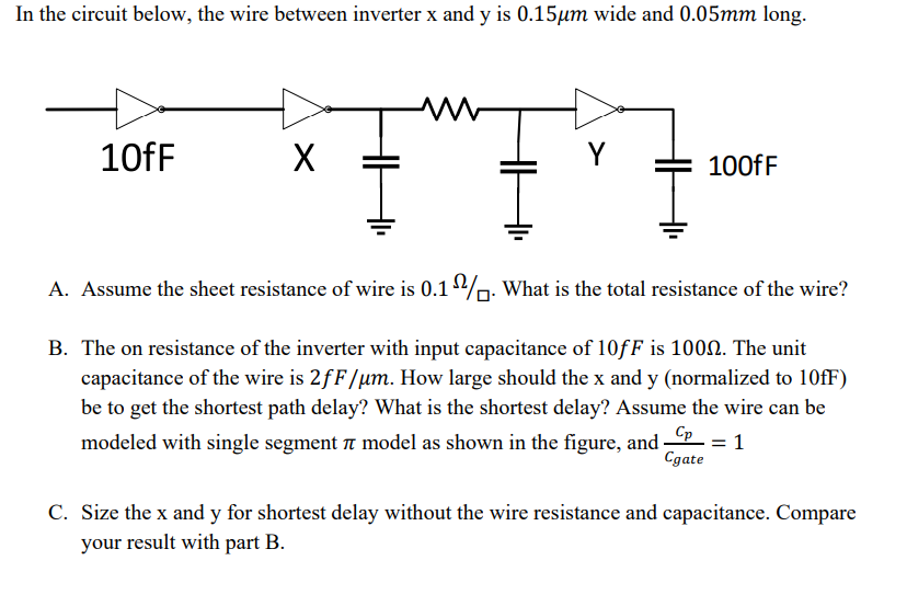
In the circuit below, the wire between inverter x and y is 0.15µm wide and 0.05mm long. 10fF X 100fF Ī A. Assume the sheet resistance of wire is 0.12%. What is the total resistance of the wire? B. The on resistance of the inverter with input capacitance of 10fF is 1000. The unit capacitance of the wire is 2fF/um. How large should the x and y (normalized to 10fF) be to get the shortest path delay? What is the shortest delay? Assume the wire can be modeled with single segment 7 model as shown in the figure, and ____ = 1 Cgate C. Size the x and y for shortest delay without the wire resistance and capacitance. Compare your result with part B.