Page 1 of 1
Question 3 The following figure shows a binary PCM signal in which the amplitude levels of +1 and -1 volt are used to re
Posted: Tue May 24, 2022 8:50 am
by answerhappygod
- Question 3 The Following Figure Shows A Binary Pcm Signal In Which The Amplitude Levels Of 1 And 1 Volt Are Used To Re 1 (26.67 KiB) Viewed 25 times
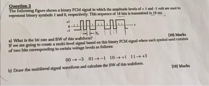
Question 3 The following figure shows a binary PCM signal in which the amplitude levels of +1 and -1 volt are used to represent binary symbols 1 and 0, respectively. This sequence of 18 bits is transmitted in 18 ms. +1 MA 144. a) What is the bit rate and BW of this wafeform? [10] Marks If we are going to create a multi-level signal based on this binary PCM signal where each symbol used consists of two bits corresponding to certain voltage levels as follows: 00-3 01-1 10+1 11 +3 b) Draw the multilevel signal waveform and calculate the BW of this wafeform. [10] Marks