Page 1 of 1
1. During loading, the offset R (same as the radius of the curved portion of the tine) of the reaction force F of the sp
Posted: Mon May 23, 2022 12:46 pm
by answerhappygod
- 1 During Loading The Offset R Same As The Radius Of The Curved Portion Of The Tine Of The Reaction Force F Of The Sp 1 (93.77 KiB) Viewed 25 times
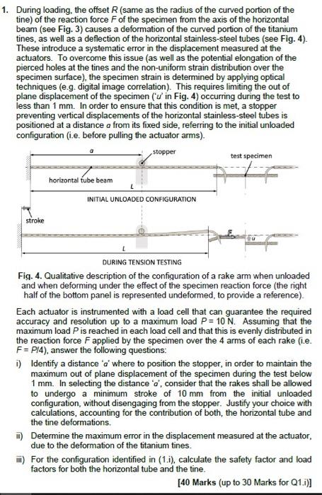
1. During loading, the offset R (same as the radius of the curved portion of the tine) of the reaction force F of the specimen from the axis of the horizontal beam (see Fig. 3) causes a deformation of the curved portion of the titanium tines, as well as a deflection of the horizontal stainless-steel tubes (see Fig. 4). These introduce a systematic error in the displacement measured at the actuators. To overcome this issue (as well as the potential elongation of the pierced holes at the tines and the non-uniform strain distribution over the specimen surface), the specimen strain is determined by applying optical techniques (e.g. digital image correlation). This requires limiting the out of plane displacement of the specimen ('u' in Fig. 4) occurring during the test to less than 1 mm. In order to ensure that this condition is met, a stopper preventing vertical displacements of the horizontal stainless-steel tubes is positioned at a distance a from its fixed side, referring to the initial unloaded configuration (i.e. before pulling the actuator arms). a stopper test specimen horizontal tube beam INITIAL UNLOADED CONFIGURATION stroke DURING TENSION TESTING Fig. 4. Qualitative description of the configuration of a rake arm when unloaded and when deforming under the effect of the specimen reaction force (the right half of the bottom panel is represented undeformed, to provide a reference). Each actuator is instrumented with a load cell that can guarantee the required accuracy and resolution up to a maximum load P= 10 N. Assuming that the maximum load P is reached in each load cell and that this is evenly distributed in the reaction force F applied by the specimen over the 4 arms of each rake (i.e. F = P/4), answer the following questions: i) Identify a distance 'a' where to position the stopper, in order to maintain the maximum out of plane displacement of the specimen during the test below 1 mm. In selecting the distance 'a', consider that the rakes shall be allowed to undergo a minimum stroke of 10 mm from the initial unloaded configuration, without disengaging from the stopper. Justify your choice with calculations, accounting for the contribution of both, the horizontal tube and the tine deformations. ii) Determine the maximum error in the displacement measured at the actuator, due to the deformation of the titanium tines. iii) For the configuration identified in (1.i), calculate the safety factor and load factors for both the horizontal tube and the tine. [40 Marks (up to 30 Marks for Q1.i)]