Page 1 of 1
The figure below shows a zero-resistance rod sliding to the right on two zero- resistance rails, which are separated by
Posted: Mon May 23, 2022 12:12 pm
by answerhappygod
- The Figure Below Shows A Zero Resistance Rod Sliding To The Right On Two Zero Resistance Rails Which Are Separated By 1 (74.79 KiB) Viewed 20 times
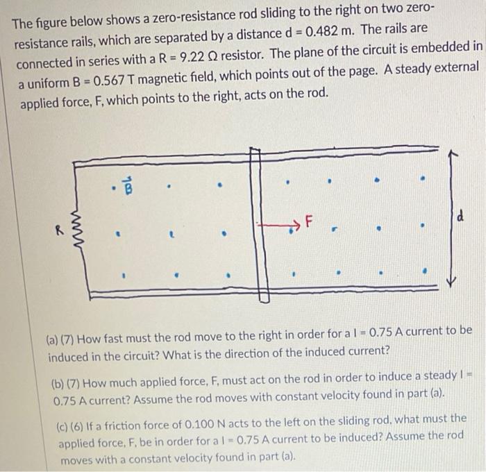
The figure below shows a zero-resistance rod sliding to the right on two zero- resistance rails, which are separated by a distance d = 0.482 m. The rails are connected in series with a R = 9.22 Q2 resistor. The plane of the circuit is embedded in a uniform B = 0.567 T magnetic field, which points out of the page. A steady external applied force, F, which points to the right, acts on the rod. R F d r (a) (7) How fast must the rod move to the right in order for a 1 = 0.75 A current to be induced in the circuit? What is the direction of the induced current? (b) (7) How much applied force, F, must act on the rod in order to induce a steady 1 = 0.75 A current? Assume the rod moves with constant velocity found in part (a). (c) (6) If a friction force of 0.100 N acts to the left on the sliding rod, what must the applied force, F, be in order for a 1-0.75 A current to be induced? Assume the rod moves with a constant velocity found in part (a). 78