Page 1 of 1
consider the logic circuit shown in Figure 1 D E F Figure 1 i. ii. iii. Write the logical expression of output X for the
Posted: Mon May 23, 2022 11:01 am
by answerhappygod
- Consider The Logic Circuit Shown In Figure 1 D E F Figure 1 I Ii Iii Write The Logical Expression Of Output X For The 1 (31.64 KiB) Viewed 30 times
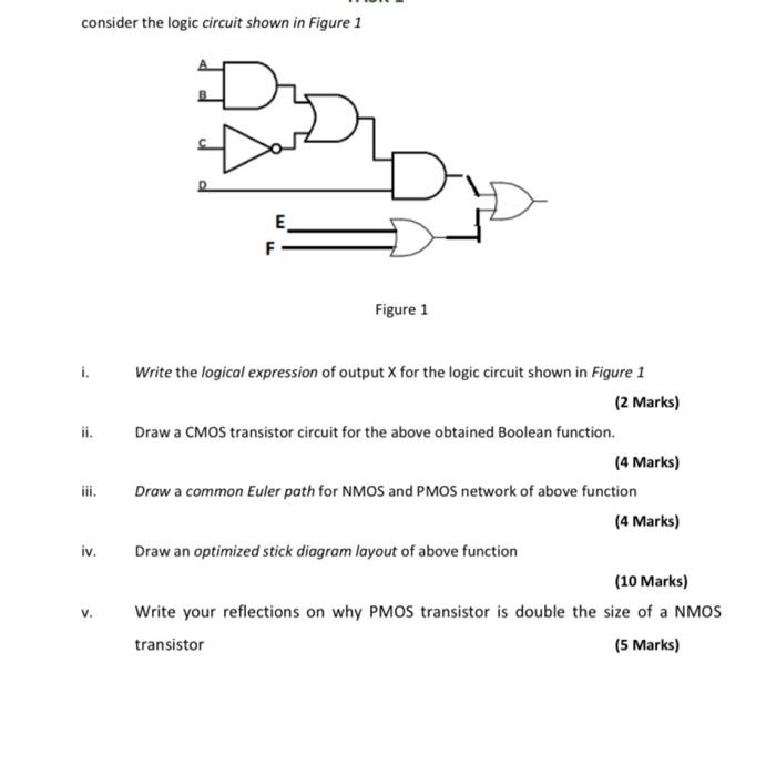
consider the logic circuit shown in Figure 1 D E F Figure 1 i. ii. iii. Write the logical expression of output X for the logic circuit shown in Figure 1 (2 Marks) Draw a CMOS transistor circuit for the above obtained Boolean function. (4 Marks) Draw a common Euler path for NMOS and PMOS network of above function (4 Marks) Draw an optimized stick diagram layout of above function (10 Marks) Write your reflections on why PMOS transistor is double the size of a NMOS transistor (5 Marks) iv.