Page 1 of 1
= As shown in Fig. 22, a resistive load R = 10 N in series with a very large inductor is supplied by a bridge rectifier
Posted: Mon May 23, 2022 10:12 am
by answerhappygod
- As Shown In Fig 22 A Resistive Load R 10 N In Series With A Very Large Inductor Is Supplied By A Bridge Rectifier 1 (458.38 KiB) Viewed 26 times
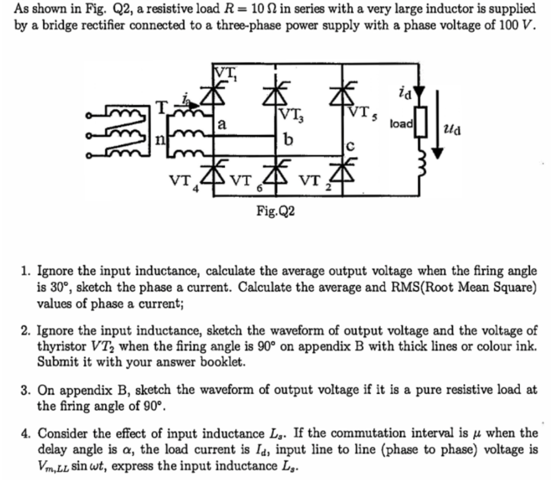
= As shown in Fig. 22, a resistive load R = 10 N in series with a very large inductor is supplied by a bridge rectifier connected to a three-phase power supply with a phase voltage of 100 V. VI id * VT, b а load ud с VT 本、 本 VT VT Fig. 22 1. Ignore the input inductance, calculate the average output voltage when the firing angle is 30°, sketch the phase a current. Calculate the average and RMS(Root Mean Square) values of phase a current; 2. Ignore the input inductance, sketch the waveform of output voltage and the voltage of thyristor VT, when the firing angle is 90° on appendix B with thick lines or colour ink. Submit it with your answer booklet. 3. On appendix B, sketch the waveform of output voltage if it is a pure resistive load at the firing angle of 90°. 4. Consider the effect of input inductance Lg. If the commutation interval is jl when the M delay angle is a, the load current is Id, input line to line (phase to phase) voltage is Vm, LL sin wt, express the input inductance Ls.