Page 1 of 1
5. A spring controlled lever is shown in Fig. 23.34. The spring is to be inserted with an initial compres- sion to produ
Posted: Sat May 21, 2022 1:23 pm
by answerhappygod
- 5 A Spring Controlled Lever Is Shown In Fig 23 34 The Spring Is To Be Inserted With An Initial Compres Sion To Produ 1 (42.16 KiB) Viewed 39 times
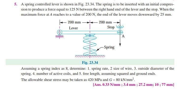
5. A spring controlled lever is shown in Fig. 23.34. The spring is to be inserted with an initial compres- sion to produce a force equal to 125 N between the right hand end of the lever and the stop. When the maximum force at A reaches to a value of 200 N, the end of the lever moves downward by 25 mm. 200 mm 200 mm Lever Stop im A Spring Fig. 23.34 Assuming a spring index as 8, determine: 1. spring rate, 2 size of wire, 3. outside diameter of the spring, 4. number of active coils, and 5. free length, assuming squared and ground ends. The allowable shear stress may be taken as 420 MPa and G = 80 kN/mm². [Ans. 0.33 N/mm ;3.4 mm ; 27.2 mm; 10 ; 77 mm) m