Page 1 of 1
Question 5 For the RC circuit shown in Fig 5, R = 6 ks2 and C = 50 uF. From time t = 0, a DC voltage v(t) = 2 V is appli
Posted: Sat May 21, 2022 11:36 am
by answerhappygod
- Question 5 For The Rc Circuit Shown In Fig 5 R 6 Ks2 And C 50 Uf From Time T 0 A Dc Voltage V T 2 V Is Appli 1 (98.07 KiB) Viewed 29 times
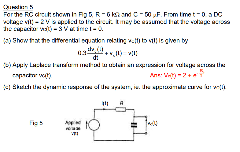
Question 5 For the RC circuit shown in Fig 5, R = 6 ks2 and C = 50 uF. From time t = 0, a DC voltage v(t) = 2 V is applied to the circuit. It may be assumed that the voltage across the capacitor vc(t) = 3 V at time t = 0. (a) Show that the differential equation relating vc(t) to v(t) is given by 0.3 dv.(t) + vo(t)= v(t) dt (b) Apply Laplace transform method to obtain an expression for voltage across the 10 capacitor vc(t). Ans: Vc(t) = 2 + et (c) Sketch the dynamic response of the system, ie. the approximate curve for vc(t). i(t) R Fig 5 ve(t) Applied voltage v(t)