Page 1 of 1
4) Consider the inverted pendulum system mounted on the vehicle shown in Figure 1. The equations of motion of this syste
Posted: Sat May 21, 2022 10:44 am
by answerhappygod
- 4 Consider The Inverted Pendulum System Mounted On The Vehicle Shown In Figure 1 The Equations Of Motion Of This Syste 1 (103.04 KiB) Viewed 21 times
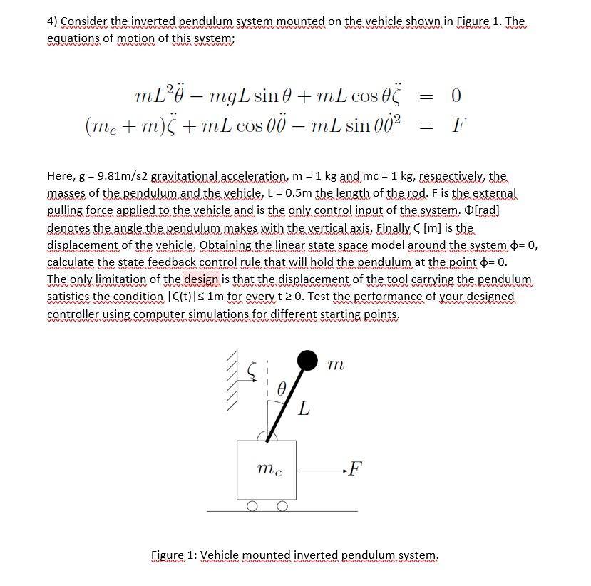
4) Consider the inverted pendulum system mounted on the vehicle shown in Figure 1. The equations of motion of this system; = 0 m[2ö – mgL sin 0 + mL cos - cos OS (me + m) 5 + mL cos – mL sin 002 m = F = = Here, g = 9.81m/s2 gravitational acceleration, m = 1 kg and mc = 1 kg, respectively, the , masses of the pendulum and the vehicle, L = 0.5m the length of the rod. F is the external pulling force applied to the vehicle and is the only control input of the system. O[rad] denotes the angle the pendulum makes with the vertical axis. Finally S [m] is the displacement of the vehicle. Obtaining the linear state space model around the system °= 0, calculate the state feedback control rule that will hold the pendulum at the point $=0. The only limitation of the design is that the displacement of the tool carrying the pendulum satisfies the condition (t)|$1m for every t 2 0. Test the performance of your designed controller using computer simulations for different starting points. т ө L mc -F Figure 1: Vehicle mounted inverted pendulum system.