Page 1 of 1
The following figure is a schematic diagram of an inverted pendulum control system using an optical encoder to measure t
Posted: Sat May 21, 2022 9:56 am
by answerhappygod
- The Following Figure Is A Schematic Diagram Of An Inverted Pendulum Control System Using An Optical Encoder To Measure T 1 (47.01 KiB) Viewed 20 times
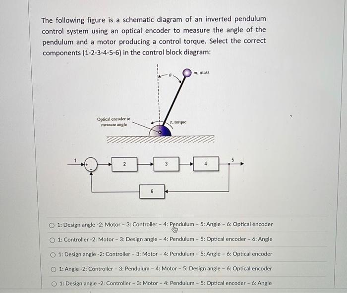
The following figure is a schematic diagram of an inverted pendulum control system using an optical encoder to measure the angle of the pendulum and a motor producing a control torque. Select the correct components (1-2-3-4-5-6) in the control block diagram: l, mass Optical encoder to measure angle T. torque 2 1: Design angle -2: Motor - 3: Controller - 4: Pendulum - 5: Angle - 6: Optical encoder 1: Controller -2: Motor - 3: Design angle - 4: Pendulum - 5: Optical encoder - 6: Angle 1: Design angle -2: Controller - 3: Motor - 4: Pendulum - 5: Angle - 6: Optical encoder 1: Angle -2: Controller - 3: Pendulum - 4: Motor - 5. Design angle - 6: Optical encoder O 1: Design angle -2: Controller - 3: Motor - 4: Pendulum - 5: Optical encoder - 6: Angle