Page 1 of 1
The mechanical system shown in Figure 4_23 is initially at rest. Att 0, a unit-step dis- placement input is applied to p
Posted: Sat May 21, 2022 9:46 am
by answerhappygod
- The Mechanical System Shown In Figure 4 23 Is Initially At Rest Att 0 A Unit Step Dis Placement Input Is Applied To P 1 (54.28 KiB) Viewed 28 times
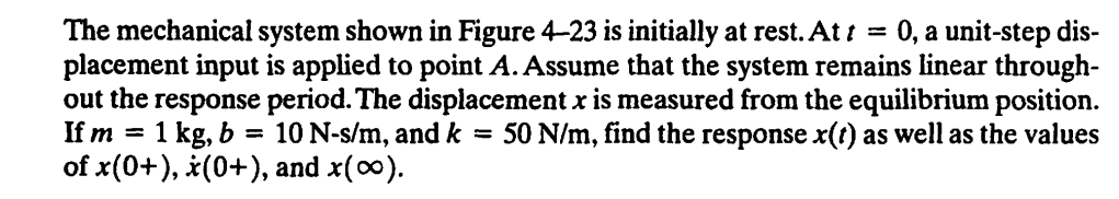
The mechanical system shown in Figure 4_23 is initially at rest. Att 0, a unit-step dis- placement input is applied to point A. Assume that the system remains linear through- out the response period. The displacement x is measured from the equilibrium position. If m = 1 kg, b = 10 N-s/m, and k = 50 N/m, find the response x(() as well as the values of x(0+), 2(0+), and x(00).
(Unit-step) input у b k m H A 7