Page 1 of 1
Q3. a) Figure Q3a shows an interfacing circuit using the 8255 in Mode 1. 5V 3302 5V OKTO KA DATA BUS FROM 8085 MPU PAZ P
Posted: Sat May 21, 2022 1:11 am
by answerhappygod
- Q3 A Figure Q3a Shows An Interfacing Circuit Using The 8255 In Mode 1 5v 3302 5v Okto Ka Data Bus From 8085 Mpu Paz P 1 (84.54 KiB) Viewed 29 times
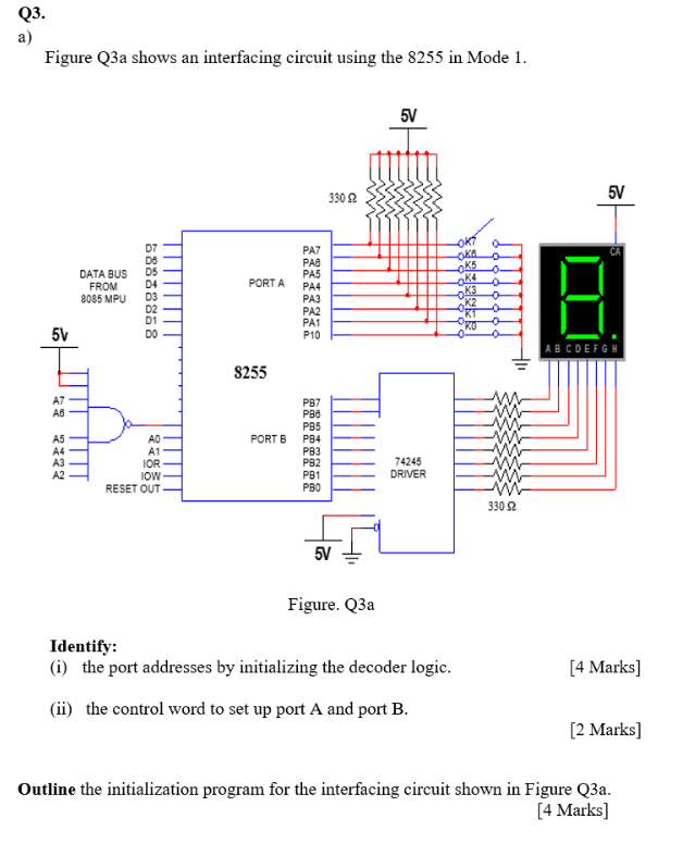
Q3. a) Figure Q3a shows an interfacing circuit using the 8255 in Mode 1. 5V 3302 5V OKTO KA DATA BUS FROM 8085 MPU PAZ PAB PA5 PA4 PA3 D4 PORTA O K5 -0. K4 0 0 KO 0 PA2 5V DO PA1 P10 ABCDEFGH H01 S255 A7 AB P97 A5 PORT 6 Pва PB5 PB4 PB3 PB2 P31 РВО AD A1 IOR IOW RESET OUT A3 A2 74245 DRIVER 3302 5V Figure. Q3a [4 Marks) Identify: (1) the port addresses by initializing the decoder logic. (ii) the control word to set up port A and port B. [2 Marks] Outline the initialization program for the interfacing circuit shown in Figure Q3a. [4 Marks]