Page 1 of 1
Q2) ) (a) A fluid level measuring instrument system comprising of a capacitive sensor and AC bridge is shown in Figure 2
Posted: Sat May 21, 2022 1:06 am
by answerhappygod
- Q2 A A Fluid Level Measuring Instrument System Comprising Of A Capacitive Sensor And Ac Bridge Is Shown In Figure 2 1 (57.6 KiB) Viewed 30 times
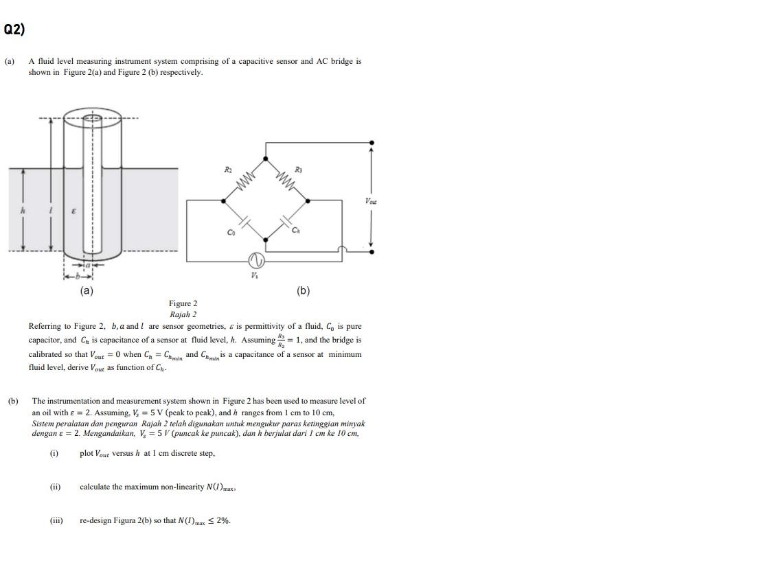
Q2) ) (a) A fluid level measuring instrument system comprising of a capacitive sensor and AC bridge is shown in Figure 2(a) and Figure 2 (b) respectively. R ww V C (a) (b) Figure 2 Rajah 2 Referring to Figure 2, b. a and I are sensor geometries, & is permittivity of a fluid, Co is pure capacitor, and Ch is capacitance of a sensor at fluid level, h. Assuming = 1, and the bridge is calibrated so that Vout = 0 when CH = Chemin and Cheminis a capacitance of a sensor at minimum fluid level, derive Vou as function of Ch (b) The instrumentation and measurement system shown in Figure 2 has been used to measure level of an oil with € = 2. Assuming. Vs = 5 V (peak to peak), and h ranges from 1 cm to 10 cm, Sistem peralatan dan penguran Rajah 2 telah digunakan untuk mengukur paras ketinggian minyak dengan € = 2. Mengandaikan, V, = 5 V (puncak ke puncak), dan h berjulat dari l cm ke 10 cm. (i) plot Vout versus h at 1 cm discrete step. (ii) calculate the maximum non-linearity N(1) max- (iii) re-design Figura 2(b) so that N()max S 2%.