Page 1 of 1
Problem3: The single-line diagram of a simple power system is shown in Figure 1. Equipment ratings and per-unit reactanc
Posted: Sat May 21, 2022 1:04 am
by answerhappygod
- Problem3 The Single Line Diagram Of A Simple Power System Is Shown In Figure 1 Equipment Ratings And Per Unit Reactanc 1 (117.89 KiB) Viewed 42 times
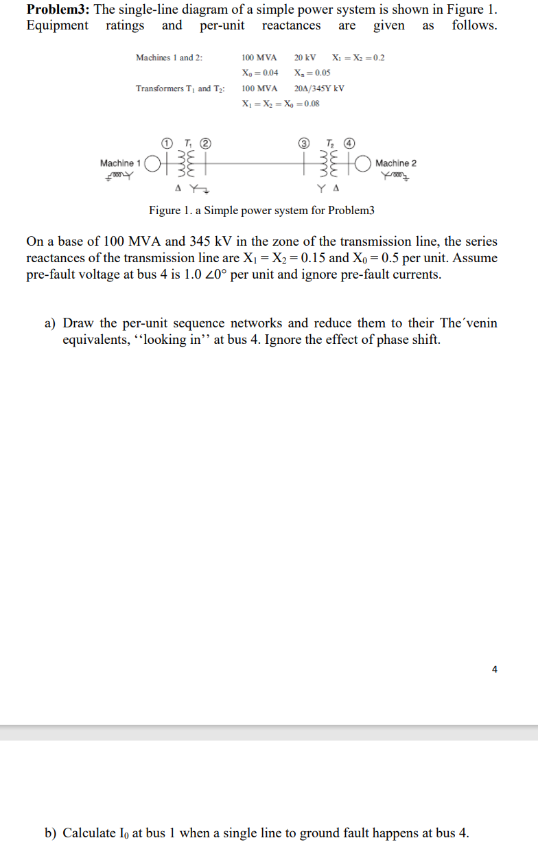
Problem3: The single-line diagram of a simple power system is shown in Figure 1. Equipment ratings and per-unit reactances given follows. are as Machines 1 and 2: 100 MVA 20 kV X = X2=0.2 X = 0.04 X = 0.05 100 MVA 204/345Y KV X = X = X =0.08 Transformers T, and T2: T. 2 3 Tz Machine 1 OF Machine 2 m$ படை ΔΥ Figure 1. a Simple power system for Problem3 On a base of 100 MVA and 345 kV in the zone of the transmission line, the series reactances of the transmission line are Xi = X2 = 0.15 and Xo = 0.5 per unit. Assume pre-fault voltage at bus 4 is 1.0 20° per unit and ignore pre-fault currents. a) Draw the per-unit sequence networks and reduce them to their The'venin equivalents, “looking in” at bus 4. Ignore the effect of phase shift. 4 b) Calculate lo at bus 1 when a single line to ground fault happens at bus 4.