Page 1 of 1
Question 3): (2.5pt) The three-phase bridge inverter in Fig. 3a is controlled by the Sinusoidal Pulse Width Modulation m
Posted: Sat May 21, 2022 1:00 am
by answerhappygod
- Question 3 2 5pt The Three Phase Bridge Inverter In Fig 3a Is Controlled By The Sinusoidal Pulse Width Modulation M 1 (123.16 KiB) Viewed 23 times
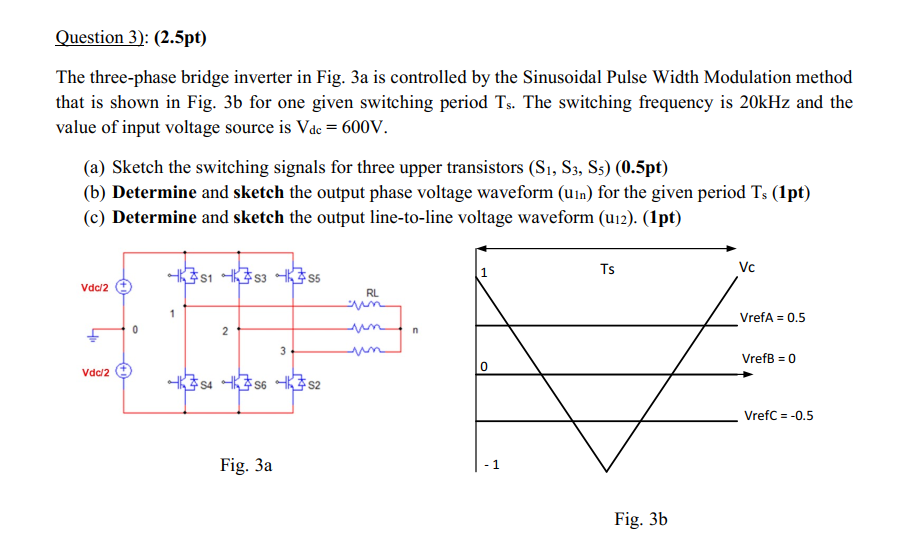
Question 3): (2.5pt) The three-phase bridge inverter in Fig. 3a is controlled by the Sinusoidal Pulse Width Modulation method that is shown in Fig. 3b for one given switching period Ts. The switching frequency is 20kHz and the value of input voltage source is Vde = 600V. (a) Sketch the switching signals for three upper transistors (S1, S3, Ss) (0.5pt) (b) Determine and sketch the output phase voltage waveform (Uin) for the given period Ts (1pt) (c) Determine and sketch the output line-to-line voltage waveform (U12). (1pt) 351 353 6785 s Ts VC Vdc/2 + RL VrefA = 0.5 2 n th 3 VrefB = 0 Vdc/2 + 74 756-6752 Vrefc = -0.5 Fig. 3a 1 Fig. 35