Page 1 of 1
B с D Out A E F F Figure 1 i. ii. Write the logical expression of output X for the logic circuit shown in Figure 1 (2 Ma
Posted: Sat May 21, 2022 12:59 am
by answerhappygod
- 1 (47.11 KiB) Viewed 26 times
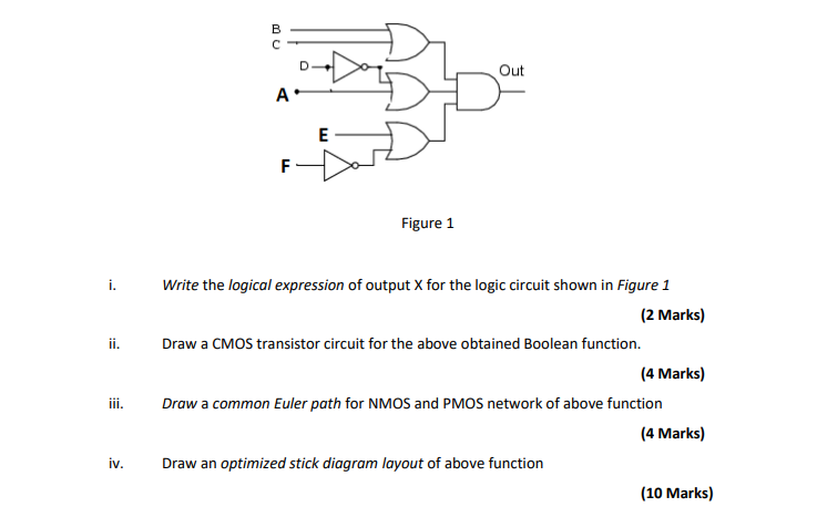
B с D Out A E F F Figure 1 i. ii. Write the logical expression of output X for the logic circuit shown in Figure 1 (2 Marks) Draw a CMOS transistor circuit for the above obtained Boolean function. (4 Marks) Draw a common Euler path for NMOS and PMOS network of above function (4 Marks) Draw an optimized stick diagram layout of above function (10 Marks) iii. iv.