Page 1 of 1
Question 8 (15 marks) Consider the circuit shown in Figure Q8(a). The op-amp is assumed to be ideal. R2 R1 Vin Vout Figu
Posted: Sat May 21, 2022 12:46 am
by answerhappygod
- Question 8 15 Marks Consider The Circuit Shown In Figure Q8 A The Op Amp Is Assumed To Be Ideal R2 R1 Vin Vout Figu 1 (37.03 KiB) Viewed 26 times
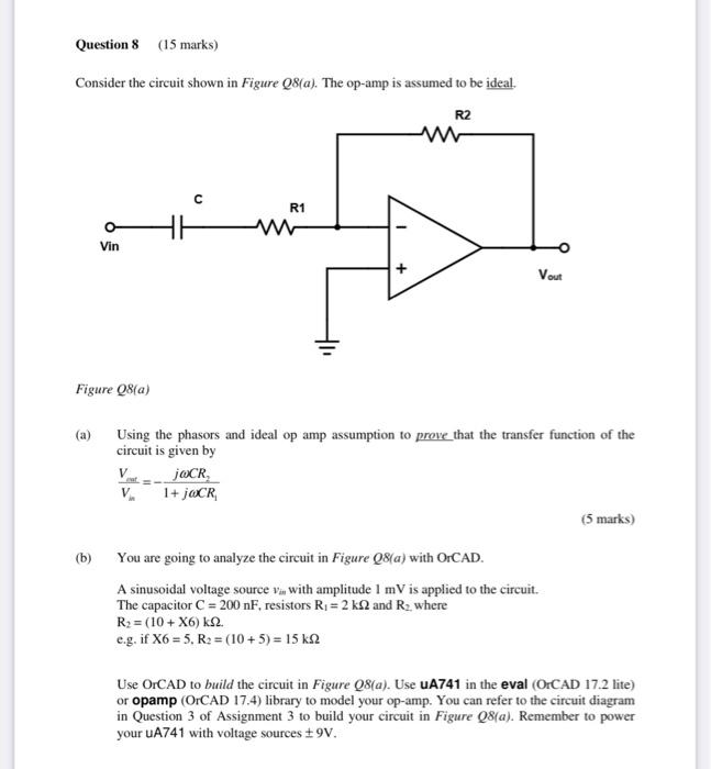
Question 8 (15 marks) Consider the circuit shown in Figure Q8(a). The op-amp is assumed to be ideal. R2 R1 Vin Vout Figure 28(a) (a) Using the phasors and ideal op amp assumption to prove_that the transfer function of the circuit is given by jOCR V 1+ OCR (5 marks) (b) You are going to analyze the circuit in Figure 28(a) with OrCAD. A sinusoidal voltage source vin with amplitude 1 mV is applied to the circuit. The capacitor C = 200 nF, resistors R = 2 k22 and R, where R2 = (10 + X6) k22. e.g. if X6 = 5, R2 = (10 + 5) = 15 k2 Use OrCAD to build the circuit in Figure 28(a). Use UA741 in the eval (OrCAD 17.2 lite) or opamp (OrCAD 17.4) library to model your op-amp. You can refer to the circuit diagram in Question 3 of Assignment 3 to build your circuit in Figure Q8(a). Remember to power your UA741 with voltage sources 9V.