Page 1 of 1
Q4 (a) An electronic filter circuit has the transfer function H1(s) defined below. Hi(s) = - 120(s + 20) S2 + 40s + 1600
Posted: Sat May 21, 2022 12:46 am
by answerhappygod
- Q4 A An Electronic Filter Circuit Has The Transfer Function H1 S Defined Below Hi S 120 S 20 S2 40s 1600 1 (1.19 MiB) Viewed 25 times
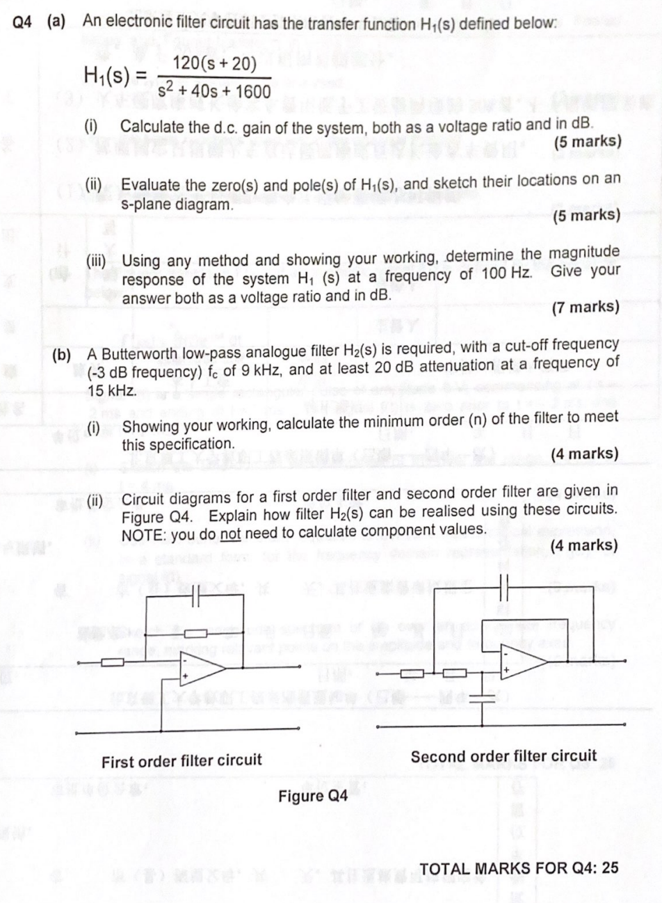
Q4 (a) An electronic filter circuit has the transfer function H1(s) defined below. Hi(s) = - 120(s + 20) S2 + 40s + 1600 () Calculate the d.c. gain of the system, both as a voltage ratio and in dB. (5 marks) (ii) Evaluate the zero(s) and pole(s) of Hy(s), and sketch their locations on an s-plane diagram (5 marks) (iii) Give your Using any method and showing your working, determine the magnitude response of the system Hi (s) at a frequency of 100 Hz. answer both as a voltage ratio and in dB. (7 marks) (b) A Butterworth low-pass analogue filter Hz(s) is required, with a cut-off frequency (-3 dB frequency) fc of 9 kHz, and at least 20 dB attenuation at a frequency of 15 kHz. (i) Showing your working, calculate the minimum order (n) of the filter to meet this specification (4 marks) (ii) Circuit diagrams for a first order filter and second order filter are given in Figure Q4. Explain how filter Hz(s) can be realised using these circuits. NOTE: you do not need to calculate component values. (4 marks) First order filter circuit Second order filter circuit Figure Q4 TOTAL MARKS FOR Q4: 25