Page 1 of 1
R3 7Ω R1 4Ω R4 1 Ω R6 1.50 ww w w w V1 R2 60 + R7 20 V2 10 V 12 V (+ R5 8Ω Figure 3: Circuit Use the mesh analysis techn
Posted: Sat May 21, 2022 12:42 am
by answerhappygod
- 1 (43.66 KiB) Viewed 23 times
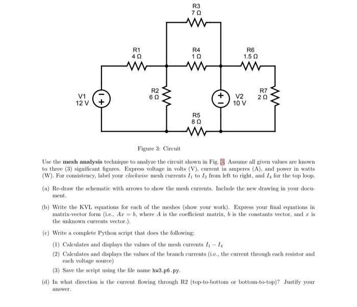
R3 7Ω R1 4Ω R4 1 Ω R6 1.50 ww w w w V1 R2 60 + R7 20 V2 10 V 12 V (+ R5 8Ω Figure 3: Circuit Use the mesh analysis technique to analyze the circuit shown in Fig. 3 Assume all given values are known to three (3) significant figures. Express voltage in volts (V), current in amperes (A), and power in watts (W). For consistency, label your clockurise mesh currents I, to iz from left to right, and I, for the top loop. (a) Re-draw the schematic with arrows to show the mesh currents. Include the new drawing in your docu- ment. (b) Write the KVL equations for each of the meshes (show your work). Express your final equations in matrix-vector form (i.e., Ax = 5, where A is the coefficient matrix, b is the constants vector, and ris the unknown currents vector.). (C) Write a complete Python script that does the following: (1) Calculates and displays the values of the mesh currents 11-14 (2) Calculates and displays the values of the branch currents (1.c., the current through each resistor and each voltage source) (3) Save the script using the file name hu3.p6.py (d) In what direction is the current flowing through R2 (top-to-bottom or bottom-to-top)? Justify your IN answer.