Page 1 of 1
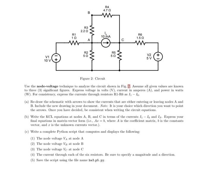
R4 4.70 B w R3 2.2 w R1 10 10 mA R6 1.50 A w R2 50 R5 5Ω V2 V1 10V w 5 V Figure 2: Circuit Use the node-voltage techniqu
Posted: Sat May 21, 2022 12:42 am
by answerhappygod
- 1 (43.68 KiB) Viewed 21 times
R4 4.70 B w R3 2.2 w R1 10 10 mA R6 1.50 A w R2 50 R5 5Ω V2 V1 10V w 5 V Figure 2: Circuit Use the node-voltage technique to analyze the circuit shown in Fig. Assume all given values are known to three (3) significant figures. Express voltage in volts (V), current in amperes (A), and power in watts (W). For consistency, express the currents through resistors R1-R6 is 11-16 (a) Re-draw the schematic with arrows to show the currents that are either entering or leaving nodes A and B. Include the new drawing in your document. Note: It is your choice which direction you want to point the arrows. Once you have decided, be consistent when writing the circuit equations. (b) Write the KCL equations at nodes A, B, and in terms of the currents 11 - 1o and Is. Express your final equations in matrix-vector form (i... Az = b, where A is the coefficient matrix, b is the constants vector, and is the unknown currents vector.). (c) Write a complete Python script that computes and displays the following: (1) The node voltage VA at node A (2) The node voltage Voy at node B (3) The node voltage Vo at node (4) The current through each of the six resistors. Be sure to specify a magnitude and a direction. (5) Save the script using the file name hw3.p5.py