Page 1 of 1
01: A single line diagram of a power system is shown in the figure below. The 3 sequence network reactances for the vari
Posted: Sat May 21, 2022 12:37 am
by answerhappygod
- 01 A Single Line Diagram Of A Power System Is Shown In The Figure Below The 3 Sequence Network Reactances For The Vari 1 (105.77 KiB) Viewed 29 times
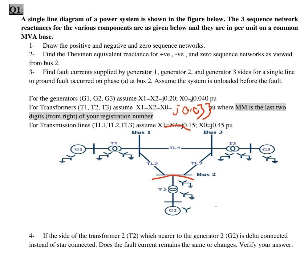
01: A single line diagram of a power system is shown in the figure below. The 3 sequence network reactances for the various components are as given below and they are in per unit on a common MVA base. 1- Draw the positive and negative and zero sequence networks. 2- Find the Thevinen equivalent reactance for +ve , -ve, and zero sequence networks as viewed from bus 2. 3- Find fault currents supplied by generator 1, generator 2, and generator 3 sides for a single line to ground fault occurred on phase (a) at bus 2. Assume the system is unloaded before the fault. For the generators (G1, G2, G3) assume X1=X2=j0.20; X0=;0.040 pu For Transformers (T1, T2, T3) assume X1=X2=X0= pu where MM is the last two digits (from right) of your registration number. For Transmission lines (TL1,TL2,TL3) assume X1-X2=;0.15; XO=j0.45 pu joczu Bus 1 Bus 3 GI TL1 G3 TL2 Bus 2 4- If the side of the transformer 2 (T2) which nearer to the generator 2 (G2) is delta connected instead of star connected. Does the fault current remains the same or changes. Verify your answer.