Page 1 of 1
Figure 4 shows the amplifier circuit using a silicon transistor. Given that VBE = 0.7 V and ß = 250. Based on a DC analy
Posted: Sat May 21, 2022 12:20 am
by answerhappygod
- Figure 4 Shows The Amplifier Circuit Using A Silicon Transistor Given That Vbe 0 7 V And Ss 250 Based On A Dc Analy 1 (31.83 KiB) Viewed 21 times
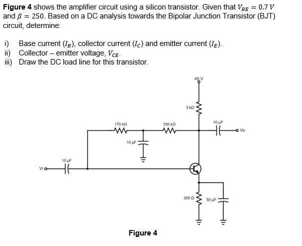
Figure 4 shows the amplifier circuit using a silicon transistor. Given that VBE = 0.7 V and ß = 250. Based on a DC analysis towards the Bipolar Junction Transistor (BJT) circuit, determine: i) Base current (IB), collector current (c) and emitter current (IE). ii) Collector - emitter voltage, VCE - iii) Draw the DC load line for this transistor. Эко ww 10 F 170 KO w 330 KO w HE Vo 10 F 10 F s HE 300 50 F 414 Figure 4