Page 1 of 1
Problem 1 – 3 points Use the following Verilog module to answer the questions below: module pb1 input clk, x, output reg
Posted: Fri May 20, 2022 11:07 pm
by answerhappygod
- Problem 1 3 Points Use The Following Verilog Module To Answer The Questions Below Module Pb1 Input Clk X Output Reg 1 (40.55 KiB) Viewed 39 times
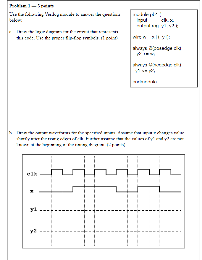
Problem 1 – 3 points Use the following Verilog module to answer the questions below: module pb1 input clk, x, output reg y1, y2); wire w = = x1(-1); a. Draw the logic diagram for the circuit that represents this code. Use the proper flip-flop symbols. (1 point) always @(posedge clk) y2 <= w; always @(negedge clk) y1 <= y2; endmodule b. Draw the output waveforms for the specified inputs. Assume that input x changes value shortly after the rising edges of clk. Further assume that the values of yl and y2 are not known at the beginning of the timing diagram. (2 points) clk X yi - - - y2 -