Page 1 of 1
(b) The 100 s2 load resistance in the two circuits of Figure Q1 requires dc voltage of 20.7 V. Assuming the diodes in bo
Posted: Fri May 20, 2022 10:57 pm
by answerhappygod
- B The 100 S2 Load Resistance In The Two Circuits Of Figure Q1 Requires Dc Voltage Of 20 7 V Assuming The Diodes In Bo 1 (68.06 KiB) Viewed 18 times
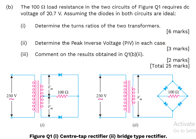
(b) The 100 s2 load resistance in the two circuits of Figure Q1 requires dc voltage of 20.7 V. Assuming the diodes in both circuits are ideal: (i) Determine the turns ratios of the two transformers. [6 marks] (ii) Determine the Peak Inverse Voltage (PIV) in each case. [3 marks] (iii) Comment on the results obtained in Q1(b)(ii). [2 marks] [Total 25 marks] 100 Ω 100 Ω' 230 V 000000000 000000 230 V clcellele eeeee (i) (ii) Activate Go to Setti Figure 21 (i) Centre-tap rectifier (ii) bridge type rectifier.