Page 1 of 1
7. You are required to design a low-loss power converter with the following characteristics and components: Vin = (10V t
Posted: Fri May 20, 2022 10:52 pm
by answerhappygod
- 7 You Are Required To Design A Low Loss Power Converter With The Following Characteristics And Components Vin 10v T 1 (55.05 KiB) Viewed 34 times
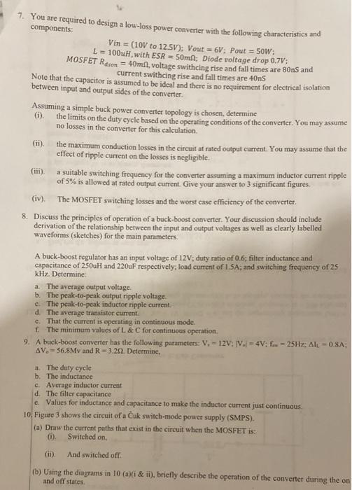
7. You are required to design a low-loss power converter with the following characteristics and components: Vin = (10V to 12.5V): Vout = 6V: Pout = SOW: L = 100uH with ESR = 50mi: Diode voltage drop 0.7V; MOSFET Reson = 40mA, voltage swithcing rise and fall times are 80ns and current swithcing rise and fall times are 40ns Note that the capacitor is assumed to be ideal and there is no requirement for electrical isolation between input and output sides of the converter Assuming a simple buck power converter topology is chosen, determine 6). the limits on the duty cycle based on the operating conditions of the converter. You may assume no losses in the converter for this calculation (11) the maximum conduction losses in the circuit at rated output current. You may assume that the effect of ripple current on the losses is negligible. a suitable switching frequency for the converter assuming a maximum inductor current ripple of 5% is allowed at rated output current. Give your answer to 3 significant figures. (iv). The MOSFET switching losses and the worst case efficiency of the converter. 8. Discuss the principles of operation of a buck-boost converter. Your discussion should include derivation of the relationship between the input and output voltages as well as clearly labelled waveforms (sketches) for the main parameters. A buck-boost regulator has an input voltage of 12V; duty ratio of 0.6; filter inductance and capacitance of 250uH and 220uF respectively, load current of 1.5A; and switching frequency of 25 kHz Determine a. The average output voltage. b. The peak-to-peak output ripple voltage. c. The peak-to-peak inductor ripple current d. The average transistor current c. That the current is operating in continuous mode. f. The minimum values of L&C for continuous operation 9. A buck-boost converter has the following parameters: V-12V: V.1 = 4V; f. = 25Hz; Ali - 0.8A AV.56.8Mv and R-3.2.2. Determine, a. The duty cycle b. The inductance c. Average inductor current d. The filter capacitance e Values for inductance and capacitance to make the inductor current just continuous 10. Figure 3 shows the circuit of a Cuk switch-mode power supply (SMPS). (a) Draw the current paths that exist in the circuit when the MOSFET is: (0) Switched on, (ii). And switched off (b) Using the diagrams in 10 (a)(i & ii), briefly describe the operation of the converter during the on and of states