Page 1 of 1
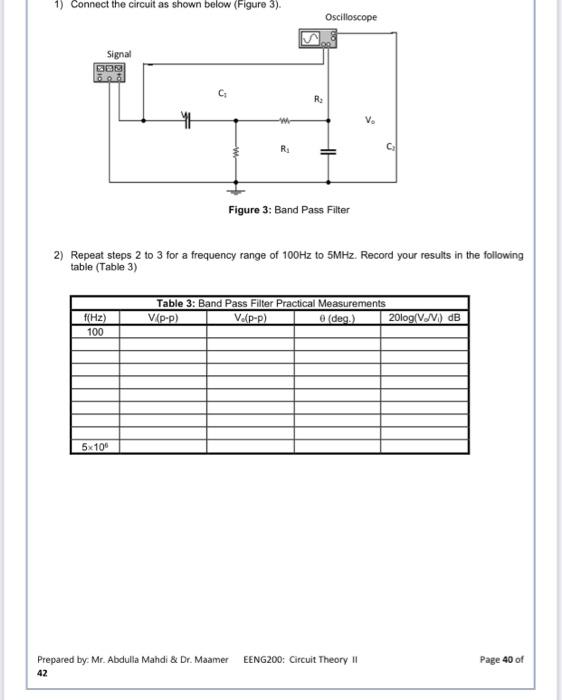
1) Connect the circuit as shown below (Figure 3). Oscilloscope Signal B09 C R: WE V RA TH Figure 3: Band Pass Filter 2)
Posted: Fri May 20, 2022 10:32 pm
by answerhappygod
- 1 Connect The Circuit As Shown Below Figure 3 Oscilloscope Signal B09 C R We V Ra Th Figure 3 Band Pass Filter 2 1 (36.66 KiB) Viewed 24 times
1) Connect the circuit as shown below (Figure 3). Oscilloscope Signal B09 C R: WE V RA TH Figure 3: Band Pass Filter 2) Repeat steps 2 to 3 for a frequency range of 100Hz to SMHz. Record your results in the following table (Table 3) f(Hz) 100 Table 3: Band Pass Filter Practical Measurements VP-P) VAP-P) e (de) 2010g/V.N) dB 5x100 EENG200: Circuit Theory II Prepared by: Mr. Abdulla Mahdi & Dr. Maamer 42 Page 40 of