Page 1 of 1
A single-line diagram of a four-bus system is shown in Figure 1. On a base of 100 MVA and 345 kV in the zone of the tran
Posted: Fri May 20, 2022 10:12 pm
by answerhappygod
- A Single Line Diagram Of A Four Bus System Is Shown In Figure 1 On A Base Of 100 Mva And 345 Kv In The Zone Of The Tran 1 (38.69 KiB) Viewed 22 times
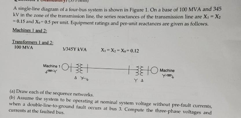
A single-line diagram of a four-bus system is shown in Figure 1. On a base of 100 MVA and 345 kV in the zone of the transmission line, the series reactances of the transmission line are Xi = X2 = 0.15 and Xo = 0.5 per unit. Equipment ratings and per-unit reactances are given as follows. Machines 1 and 2: Transformers 1 and 2: 100 MVA V345Y KVA Xi = X2 = Xo = 0.12 Machine 1 Frony OTE TETO Machine yoon AM Υ Δ (a) Draw each of the sequence networks. (b) Assume the system to be operating at nominal system voltage without pre-fault currents, when a double-line-to-ground fault occurs at bus 3. Compute the three-phase voltages and currents at the faulted bus.