Page 1 of 1
Question 1 (a) Interpret the circuit given in Figure Q1(a) using the basic diode theory and answer the following questio
Posted: Fri May 20, 2022 8:52 pm
by answerhappygod
- Question 1 A Interpret The Circuit Given In Figure Q1 A Using The Basic Diode Theory And Answer The Following Questio 1 (121.72 KiB) Viewed 50 times
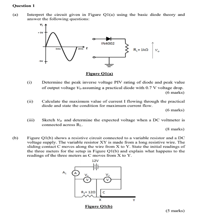
Question 1 (a) Interpret the circuit given in Figure Q1(a) using the basic diode theory and answer the following questions: V h IN4002 A 2mst R = 162 V. (i) Figure Q1(a) Determine the peak inverse voltage PIV rating of diode and peak value of output voltage Vo assuming a practical diode with 0.7 V voltage drop. (6 marks) Calculate the maximum value of current I flowing through the practical diode and state the condition for maximum current flow. (6 marks) (ii) (b) (iii) Sketch Vo and determine the expected voltage when a DC voltmeter is connected across RL. (8 marks) Figure Q1(b) shows a resistive circuit connected to a variable resistor and a DC voltage supply. The variable resistor XY is made from a long resistive wire. The sliding contact C moves along the wire from X to Y. State the initial readings of the three meters for the setup in Figure Q1(b) and explain what happens to the readings of the three meters as C moves from X to Y. 12V HIE Ri= 1202 с х Figure Q1(b) (5 marks)