Page 1 of 1
2- Consider the receiver system shown in Figure 1. Let the received carrier generate a voltage of 1 mVrms across the ant
Posted: Fri May 20, 2022 7:59 pm
by answerhappygod
- 2 Consider The Receiver System Shown In Figure 1 Let The Received Carrier Generate A Voltage Of 1 Mvrms Across The Ant 1 (28.96 KiB) Viewed 91 times
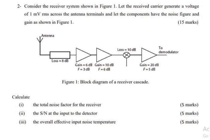
2- Consider the receiver system shown in Figure 1. Let the received carrier generate a voltage of 1 mVrms across the antenna terminals and let the components have the noise figure and gain as shown in Figure 1. (15 marks) Antenna Loss = 10 dB To demodulator Loss 8 dB Gain-6dB Gain -10 dB F-3dB F-6 dB Gain - 20 dB F-5 dB Figure 1: Block diagram of a receiver cascade. Calculate (i) the total noise factor for the receiver (ii) the S/N at the input to the detector (iii) the overall effective input noise temperature (5 marks) (5 marks) (5 marks) Ас Go