Page 1 of 1
The transfer functions of the control system shown in Figure Q1a are as follows: Gc(S) = K (s + 3)2 Gp(s) = (s +5) (s +
Posted: Fri May 20, 2022 7:31 pm
by answerhappygod
- The Transfer Functions Of The Control System Shown In Figure Q1a Are As Follows Gc S K S 3 2 Gp S S 5 S 1 (77.4 KiB) Viewed 49 times
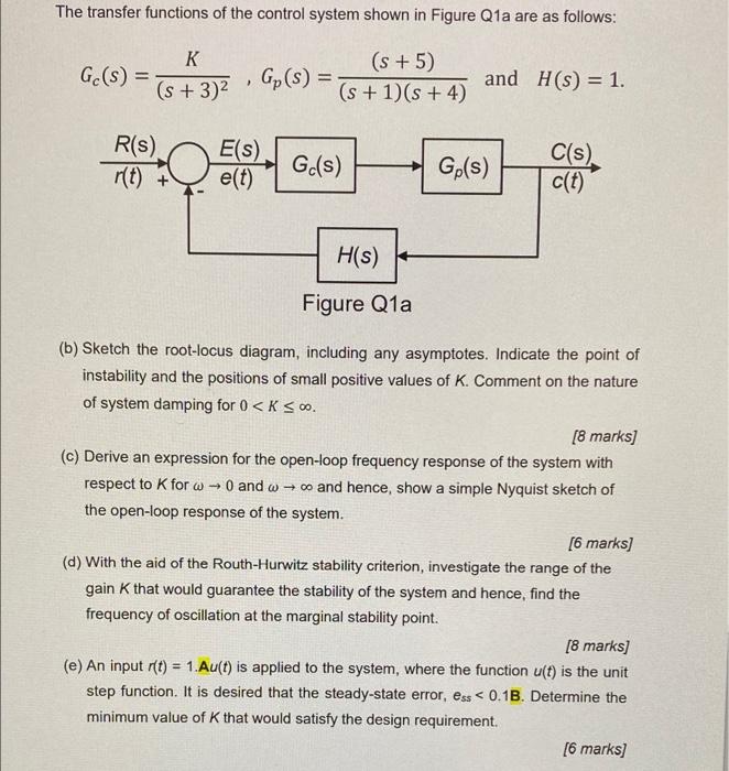
The transfer functions of the control system shown in Figure Q1a are as follows: Gc(S) = K (s + 3)2 Gp(s) = (s +5) (s + 1)(s + 4) 2 and H(S) = 1. E(s) R(S) r(t) + 0 Gc(s) e(t) Ge(s) C(s) c(t) H(S) Figure Q1a (b) Sketch the root-locus diagram, including any asymptotes. Indicate the point of instability and the positions of small positive values of K. Comment on the nature of system damping for 0 <K SO. (8 marks] (c) Derive an expression for the open-loop frequency response of the system with respect to K for O and wo and hence, show a simple Nyquist sketch of the open-loop response of the system. [6 marks] (d) With the aid of the Routh-Hurwitz stability criterion, investigate the range of the gain that would guarantee the stability of the system and hence, find the frequency of oscillation at the marginal stability point. [8 marks] (e) An input r(t) = 1.Au(t) is applied to the system, where the function u(t) is the unit step function. It is desired that the steady-state error, ess < 0.13. Determine the minimum value of that would satisfy the design requirement. [6 marks] =