Page 1 of 1
Z 2 2 250m R R Figure 3 (b) Figure 3 (b) shows two towers (1 and 2) of a transmission line, which are joined by overhead
Posted: Fri May 20, 2022 7:31 pm
by answerhappygod
- Z 2 2 250m R R Figure 3 B Figure 3 B Shows Two Towers 1 And 2 Of A Transmission Line Which Are Joined By Overhead 1 (34.36 KiB) Viewed 44 times
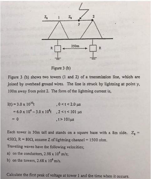
Z 2 2 250m R R Figure 3 (b) Figure 3 (b) shows two towers (1 and 2) of a transmission line, which are joined by overhead ground wires. The line is struck by lightning at point y 100m away from point 2. The form of the lightning current is, I(t) = 3.0 x 100 .0<t<2.0 us = 6.0 x 10^-3.0 x 10't ,2<t<101 us = 0 ,> 101 us Each tower is 30m tall and stands on a square base with a 8m side. ZE = 45092, R = 8092, assume Z of lightning channel - 1500 ohm. Traveling waves have the following velocities; a) on the conductors, 2.98 x 10 m/s; b) on the towers, 2.68 x 10 m/s. Calculate the first peak of voltage at tower 1 and the time when it occurs.