Page 1 of 1
Systems Modelling & Control Tutorial 2 Section B Question 5 For the RC circuit shown in Fig 5, R = 6 k and C = 50 uF. Fr
Posted: Fri May 20, 2022 7:21 pm
by answerhappygod
- Systems Modelling Control Tutorial 2 Section B Question 5 For The Rc Circuit Shown In Fig 5 R 6 K And C 50 Uf Fr 1 (184.04 KiB) Viewed 40 times
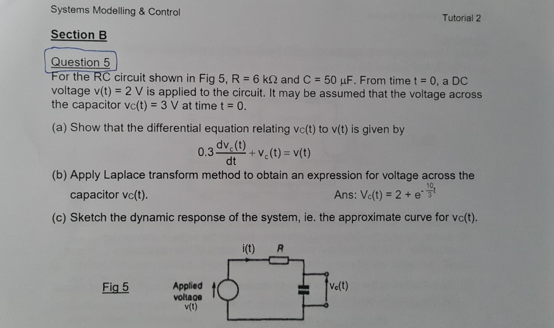
Systems Modelling & Control Tutorial 2 Section B Question 5 For the RC circuit shown in Fig 5, R = 6 k and C = 50 uF. From time t = 0, a DC voltage v(t) = 2 V is applied to the circuit. It may be assumed that the voltage across the capacitor vc(t) = 3 V at time t = 0. (a) Show that the differential equation relating vc(t) to v(t) is given by 0.3 dv.(t) +ve(t) = v(t) 10 dt (b) Apply Laplace transform method to obtain an expression for voltage across the capacitor vo(t). Ans: Vc(t) = 2 + 3 (c) Sketch the dynamic response of the system, ie, the approximate curve for vc(t). i(t) R Fig 5 fve(t) Applied voltage v(t)