Page 1 of 1
C2 HE no 10 20 3o 40 50 BO 7 0 OB 09 - 10 011 012 13 220 E ЕТЕТ +5V - U1 PDORXDIP CINT16 PBOCP1/CLKOIPCINTO 10 PD1/TXDAP
Posted: Fri May 20, 2022 7:03 pm
by answerhappygod
- 1 (125.13 KiB) Viewed 49 times
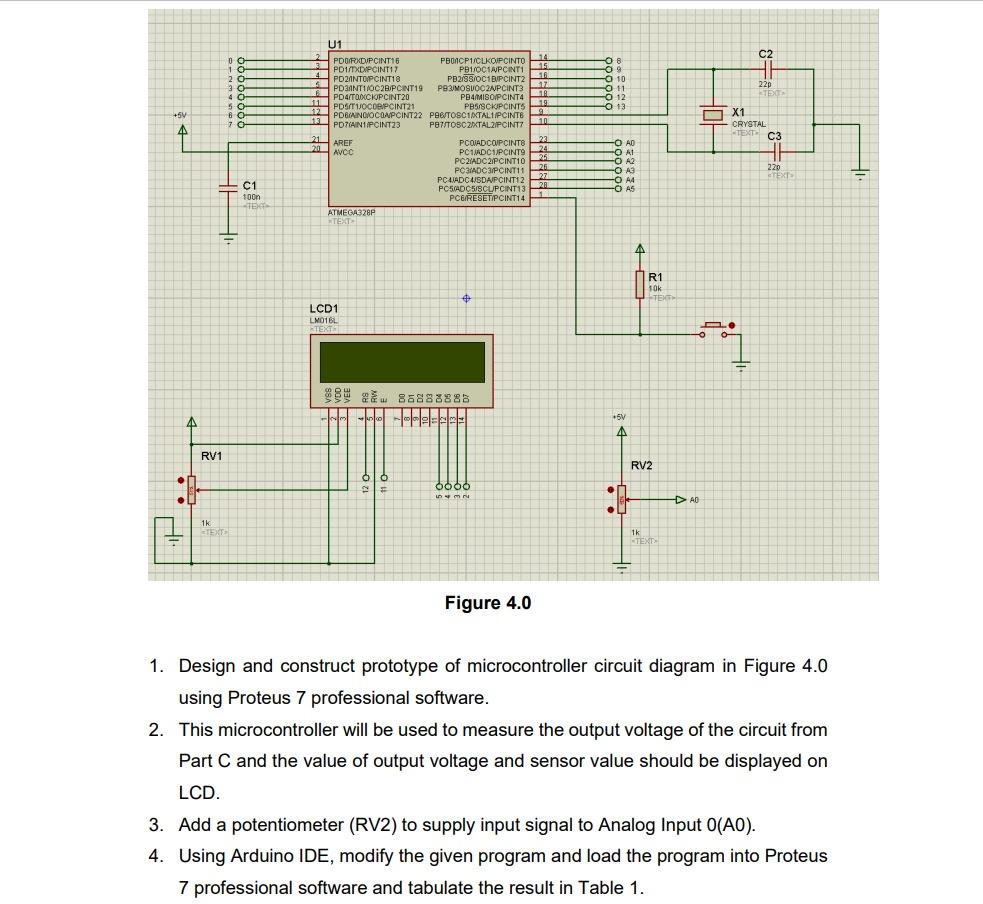
C2 HE no 10 20 3o 40 50 BO 7 0 OB 09 - 10 011 012 13 220 E ЕТЕТ +5V - U1 PDORXDIP CINT16 PBOCP1/CLKOIPCINTO 10 PD1/TXDAPCINT17 PB1/OCTAPCINTI 15 4 HPDIINTOIPCINT18 PB2/SS/OCBIPCINT2-16 5 PD3ANTIOC2BUPCINT19 POZIMOSVOC2APCINT3 317 18 PD4/TOMOCIOPCINT20 PB4MAISO/PCINT4 11 POSITIJOCORPCINT21 PB5/SCRIPCINTS 119 12 PDBIANCIOCOMPCINT22 PBB TOSCIXTAL1IPCINTE 9 13 POTAINTIPCINT23 PBT/TOSC ZIXTAL2IPCINT710 A1 AREF PCOUADCOPCINTS 23 22 201 AVCC PCIADCHIPCINTO 2 24 PCRIADC2IPCINT10 26 PCIADC3PCINT11 26 PCIADCASDAPCINT12 27 POSADCISCUPCINT13 20 PCG/RESETIPCINT14 ATMEGA328P TEXT X1 CRYSTAL TENT C3 A HI -O AD OA O A2 O A3 - A4 -O AS 220 TEXT C1 100n -TEX - R1 10K TEXT LCD1 LMO16L TEXT D. 1 98986888888 00 ellel +5V AN RV1 RV2 6000 M :01 DAD 1k TE 1k STEXT Figure 4.0 1. Design and construct prototype of microcontroller circuit diagram in Figure 4.0 using Proteus 7 professional software. 2. This microcontroller will be used to measure the output voltage of the circuit from Part C and the value of output voltage and sensor value should be displayed on LCD. 3. Add a potentiometer (RV2) to supply input signal to Analog Input 0(AO). 4. Using Arduino IDE, modify the given program and load the program into Proteus 7 professional software and tabulate the result in Table 1.