Page 1 of 1
2. (a) Consider the circuit shown in Figure Q2(a) and assume the diodes to be ideal. R1 W D D2 R2 w Vi R3 V2 w Figure Q2
Posted: Fri May 20, 2022 7:03 pm
by answerhappygod
- 2 A Consider The Circuit Shown In Figure Q2 A And Assume The Diodes To Be Ideal R1 W D D2 R2 W Vi R3 V2 W Figure Q2 1 (88.34 KiB) Viewed 35 times
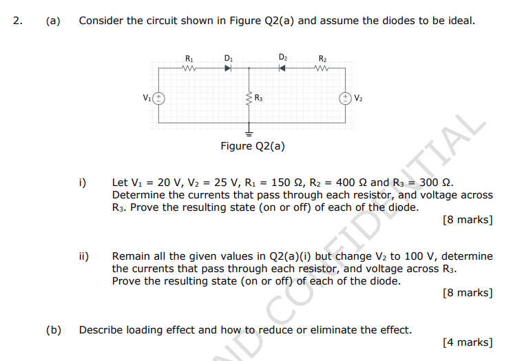
2. (a) Consider the circuit shown in Figure Q2(a) and assume the diodes to be ideal. R1 W D D2 R2 w Vi R3 V2 w Figure Q2(a) i) Let V1 = 20 V, V2 = 25 V, R2 = 150 2, R2 = 400 2 and R3 = 300 2. Determine the currents that pass through each resistor, and voltage across R3. Prove the resulting state (on or off) of each of the diode. [8 marks] TIAL ii) Remain all the given values in Q2(a)(i) but change V2 to 100 v, determine the currents that pass through each resistor, and voltage across R3. Prove the resulting state (on or off) of each of the diode. [8 marks] (b) Describe loading effect and how to reduce or eliminate the effect. Coor [4 marks]