Page 1 of 1
3. The circuit shown in Fig. Q3 is a single-phase half-wave controlled rectifier operating from a 240V, 50Hz supply, Giv
Posted: Fri May 20, 2022 6:58 pm
by answerhappygod
- 3 The Circuit Shown In Fig Q3 Is A Single Phase Half Wave Controlled Rectifier Operating From A 240v 50hz Supply Giv 1 (43.87 KiB) Viewed 53 times
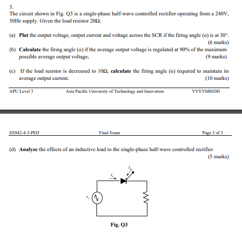
3. The circuit shown in Fig. Q3 is a single-phase half-wave controlled rectifier operating from a 240V, 50Hz supply, Given the load resistor 2002: (a) Plot the output voltage, output current and voltage across the SCR if the firing angle (a) is at 30°. (6 marks) (b) Calculate the firing angle (a) if the average output voltage is regulated at 90% of the maximum possible average output voltage. (9 marks) (C) If the load resistor is decreased to 106, calculate the firing angle (a) required to maintain its average output current. (10 marks) APU Level 3 Asia Pacific University of Technology and Innovation YYYYMMDD EE042-4-3-PED Final Exam Page 3 of 3 (d) Analyze the effects of an inductive load to the single-phase half-wave controlled rectifier. (5 marks) Fig. 23