Page 1 of 1
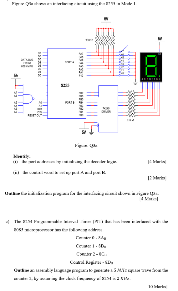
Figure Q3a shows an interfacing circuit using the 8255 in Mode 1. 5V 33022 5V 0 OKAO DATA BUS FROM 8085 MPU PORTA 898828
Posted: Fri May 20, 2022 6:51 pm
by answerhappygod
- Figure Q3a Shows An Interfacing Circuit Using The 8255 In Mode 1 5v 33022 5v 0 Okao Data Bus From 8085 Mpu Porta 898828 1 (98.43 KiB) Viewed 45 times
Figure Q3a shows an interfacing circuit using the 8255 in Mode 1. 5V 33022 5V 0 OKAO DATA BUS FROM 8085 MPU PORTA 89882889 PAZ PAD PAS PA4 РАЗ PA2 PA1 P10 OKS O. K4 -o 03 0 K2 0 0 5V ABCDEFGH S255 AZ AD PORT 6 2222 AD A1 IOR IOW RESET OUT P87 PSO P85 P94 PS3 PS2 P91 PSO 74245 DRIVER 3302 5V Figure. Q3a Identify: (1) the port addresses by initializing the decoder logic. (ii) the control word to set up port A and port B. [4 Marks) [2 marks] Outline the initialization program for the interfacing circuit shown in Figure Q3a. [4 Marks] c) The 8254 Programmable Interval Timer (PIT) that has been interfaced with the 8085 microprocessor has the following address. Counter 0-8AH Counter 1 - 8BH Counter 2 - SCH Control Register - SDH Outline an assembly language program to generate a 5 MHz square wave from the counter 2, by assuming the clock frequency of 8254 is 2 KHz. [10 Marks]