Page 1 of 1
C P3: In the figure, R1 = 10 kN, R2 = 15 kN, C = 0.4 pF, and the ideal battery has emf E= 20 V. First, the switch is clo
Posted: Wed May 18, 2022 9:03 am
by answerhappygod
- C P3 In The Figure R1 10 Kn R2 15 Kn C 0 4 Pf And The Ideal Battery Has Emf E 20 V First The Switch Is Clo 1 (147.88 KiB) Viewed 74 times
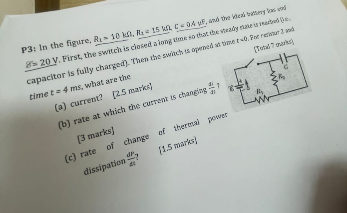
C P3: In the figure, R1 = 10 kN, R2 = 15 kN, C = 0.4 pF, and the ideal battery has emf E= 20 V. First, the switch is closed a long time so that the steady state is reached (i.e. capacitor is fully charged). Then the switch is opened at time t =0. For resistor 2 and time t = 4 ms, what are the [Total 7 marks) (a) current? [2.5 marks] (b) rate at which the current is changing ? 8 dt R W dP [3 marks] (c) rate of change of thermal power dissipation ? [1.5 marks] dc