Page 1 of 1
3 Figure 3.1 shows a circuit that was used by a student to measure the total resistance of three resistors R. R, and Rg
Posted: Wed May 18, 2022 8:22 am
by answerhappygod
- 3 Figure 3 1 Shows A Circuit That Was Used By A Student To Measure The Total Resistance Of Three Resistors R R And Rg 1 (33.08 KiB) Viewed 52 times
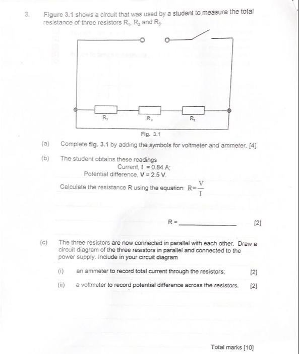
3 Figure 3.1 shows a circuit that was used by a student to measure the total resistance of three resistors R. R, and Rg R, R R Fig. 3.1 (a) Complete fig. 3.1 by adding the symbols for voltmeter and ammeter. [4] (b) The student obtains these readings Current, I = 0.84 A Potential difference. V = 2.5 V. Calculate the resistance R using the equation: R-V R= [2] c The three resistors are now connected in parallel with each other. Draw a circuit diagram of the three resistors in parallel and connected to the power supply. Include in your circuit diagram (0) an ammeter to record total current through the resistors [2] (1) a voltmeter to record potential difference across the resistors [2] Total marks (10)