Page 1 of 1
3 (a) C1=15 F C-3 uF TH C. 20 uF HQ II ( 6 °F FIGURE 3 FIGURE 3 shows an arrangement of four capacitors. The voltage acr
Posted: Wed May 18, 2022 6:45 am
by answerhappygod
- 3 A C1 15 F C 3 Uf Th C 20 Uf Hq Ii 6 F Figure 3 Figure 3 Shows An Arrangement Of Four Capacitors The Voltage Acr 1 (332.25 KiB) Viewed 43 times
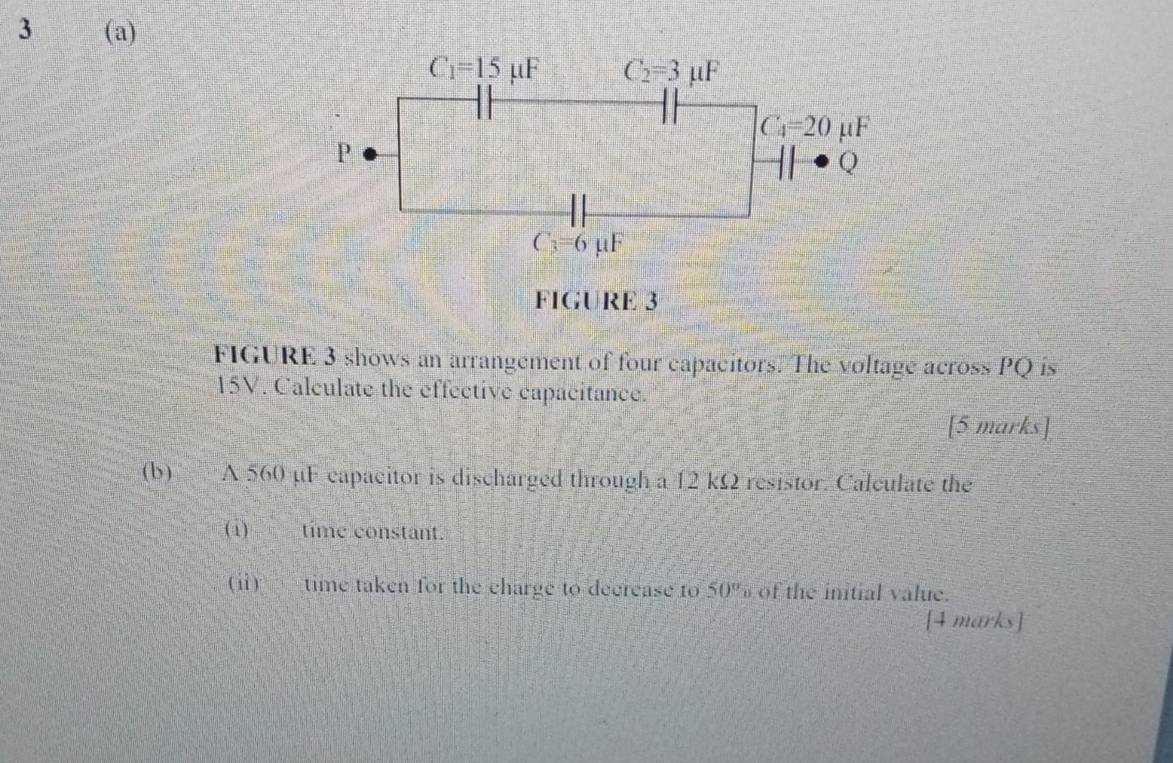
3 (a) C1=15 F C-3 uF TH C. 20 uF HQ II ( 6 °F FIGURE 3 FIGURE 3 shows an arrangement of four capacitors. The voltage across PQ is 15V. Calculate the effective capacitance. [5 marks (by A 560 ut capacitor is discharged through a 12 k12 resistor. Calculate the time constant. BE time taken for the charge to decrease 10 50's of the initial value. 4 marks)