Page 1 of 1
1mH ipt + VL 11 Vin + VD + Vc 2. The following converter is controlled by means of a Pl controller C(s) = kn + , which i
Posted: Tue May 17, 2022 9:26 pm
by answerhappygod
- 1mh Ipt Vl 11 Vin Vd Vc 2 The Following Converter Is Controlled By Means Of A Pl Controller C S Kn Which I 1 (123.49 KiB) Viewed 80 times
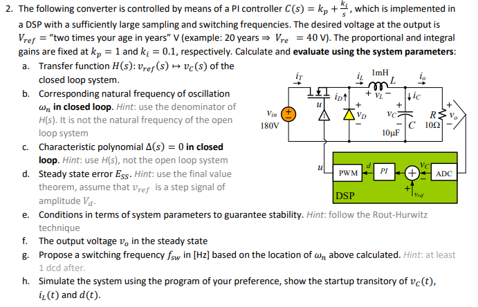
1mH ipt + VL 11 Vin + VD + Vc 2. The following converter is controlled by means of a Pl controller C(s) = kn + , which is implemented in a DSP with a sufficiently large sampling and switching frequencies. The desired voltage at the output is Vref = "two times your age in years" V (example: 20 years = Vre = 40 V). The proportional and integral gains are fixed at kp = 1 and ki = 0.1, respectively. Calculate and evaluate using the system parameters: a. Transfer function H(s): Vref(s) > vc(s) of the closed loop system. ; b. Corresponding natural frequency of oscillation Hic Wy in closed loop. Hint: use the denominator of R?v H(s). It is not the natural frequency of the open 180V C 1022 loop system 10 F C. Characteristic polynomial A(s) = 0 in closed loop. Hint: use H(s), not the open loop system d. Steady state error Ess. Hint: use the final value PWM ADC theorem, assume that Vref is a step signal of amplitude Vd. DSP e. Conditions in terms of system parameters to guarantee stability. Hint: follow the Rout-Hurwitz technique f. The output voltage v, in the steady state 8. Propose a switching frequency fsw in [Hz] based on the location of Wn above calculated. Hint: at least 1 dcd after h. Simulate the system using the program of your preference, show the startup transitory of vc(t), iz(t) and d(t). PI