Page 1 of 1
Figure 5.1 represents an idealization of a turbofan engine. A steady air flow moves through two concentric cylindrical d
Posted: Tue May 17, 2022 8:39 pm
by answerhappygod
- Figure 5 1 Represents An Idealization Of A Turbofan Engine A Steady Air Flow Moves Through Two Concentric Cylindrical D 1 (83.4 KiB) Viewed 84 times
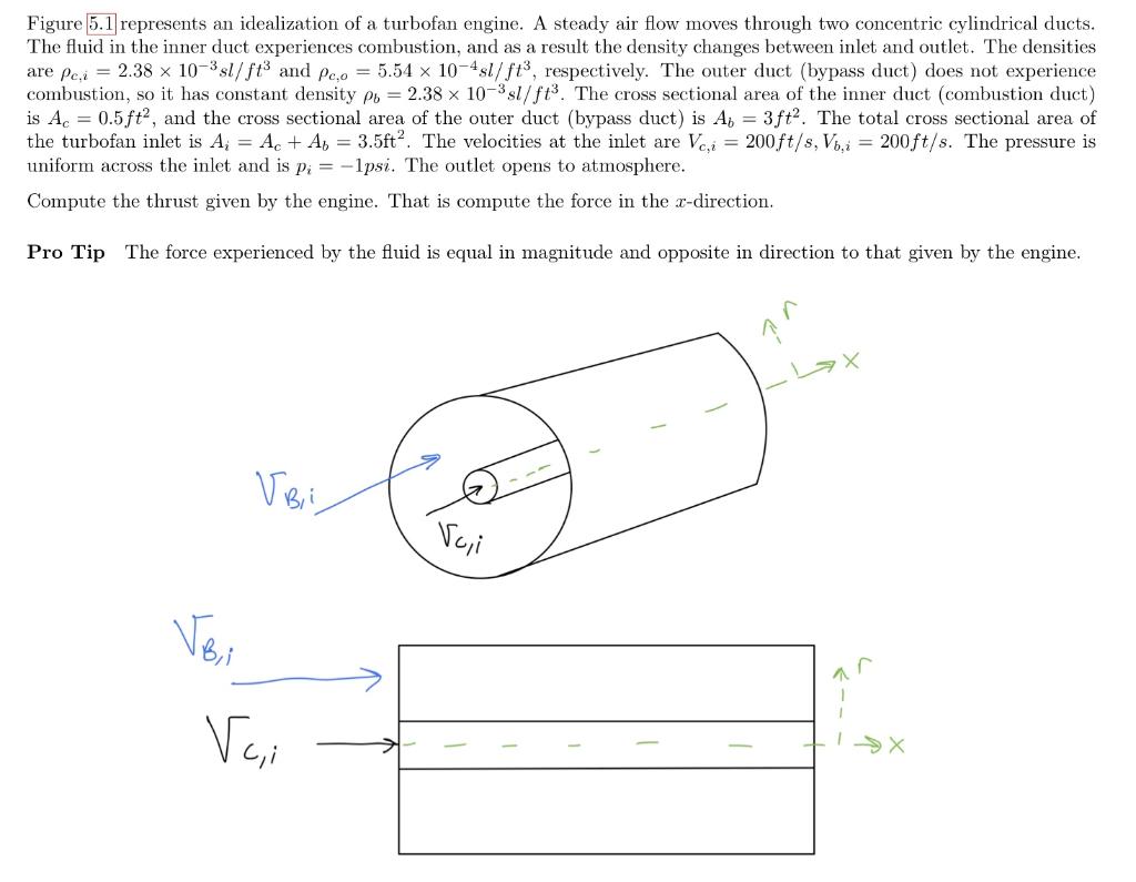
Figure 5.1 represents an idealization of a turbofan engine. A steady air flow moves through two concentric cylindrical ducts. The fluid in the inner duct experiences combustion, and as a result the density changes between inlet and outlet. The densities are pei = 2.38 x 10⁻³⁵l/ft and Pea = 5.54 x 10-451/ft, respectively. The outer duct (bypass duct) does not experience combustion, so it has constant density po = 2.38 x 10⁻³sl/fts. The cross sectional area of the inner duct (combustion duct) is Ac = 0.5ft?, and the cross sectional area of the outer duct (bypass duct) is Aj = 3ft?. The total cross sectional area of the turbofan inlet is A; = Ac + A1 = 3.5ft. The velocities at the inlet are Vc,i = 200ft/s, Vo, i = 200ft/s. The pressure is uniform across the inlet and is pi = -1psi. The outlet opens to atmosphere. Compute the thrust given by the engine. That is compute the force in the x-direction. Pro Tip The force experienced by the fluid is equal in magnitude and opposite in direction to that given by the engine. Voi Voi Voi 不 1 Vai