Page 1 of 1
Electronics students are learning to use phasor diagrams to analyze RLC series circuits. They are given the following ph
Posted: Mon May 16, 2022 6:27 pm
by answerhappygod
- Electronics Students Are Learning To Use Phasor Diagrams To Analyze Rlc Series Circuits They Are Given The Following Ph 1 (29.04 KiB) Viewed 103 times
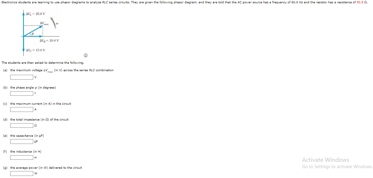
Electronics students are learning to use phasor diagrams to analyze RLC series circuits. They are given the following phasor diagram, and they are told that the AC power source has a frequency of 50.0 Hz and the resistor has a resistance of 50.5 0. AV. = 25.0 V AV 0 AV = 20.0 V AVc = 15.0 V The students are then asked to determine the following. (a) the maximum voltage AVmax (in V) across the series RLC combination v (b) the phase angle « (in degrees) (c) the maximum current (in A) in the circuit A (d) the total impedance (in 2) of the circuit 0 (e) the capacitance in PF) UF (f) the inductance (in H) H Activate Windows Go to Settings to activate Windows, (9) the average power in W) delivered to the circuit w