Page 1 of 1
An electrical engineer designed an RL circuit similar to the one shown in the figure, with a = 6.00 V, L = 3.60 ml, and
Posted: Mon May 16, 2022 4:20 pm
by answerhappygod
- An Electrical Engineer Designed An Rl Circuit Similar To The One Shown In The Figure With A 6 00 V L 3 60 Ml And 1 (40.61 KiB) Viewed 31 times
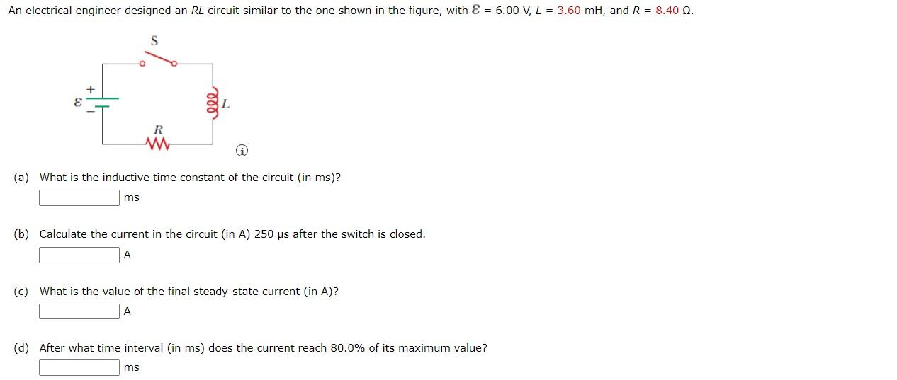
An electrical engineer designed an RL circuit similar to the one shown in the figure, with a = 6.00 V, L = 3.60 ml, and R = 8.40 0. + R W (a) What is the inductive time constant of the circuit (in ms)? ms (b) Calculate the current in the circuit (in A) 250 us after the switch is closed. A (c) What is the value of the final steady-state current in A)? A (d) After what time interval (in ms) does the current reach 80.0% of its maximum value? ms