Page 1 of 1
Consider the capacitor arrangement in the figure, with C1 = 2.9 MF, C2 = 1.8 uF and C3=2.4 °F and a potential difference
Posted: Mon May 16, 2022 3:34 pm
by answerhappygod
- Consider The Capacitor Arrangement In The Figure With C1 2 9 Mf C2 1 8 Uf And C3 2 4 F And A Potential Difference 1 (44.82 KiB) Viewed 21 times
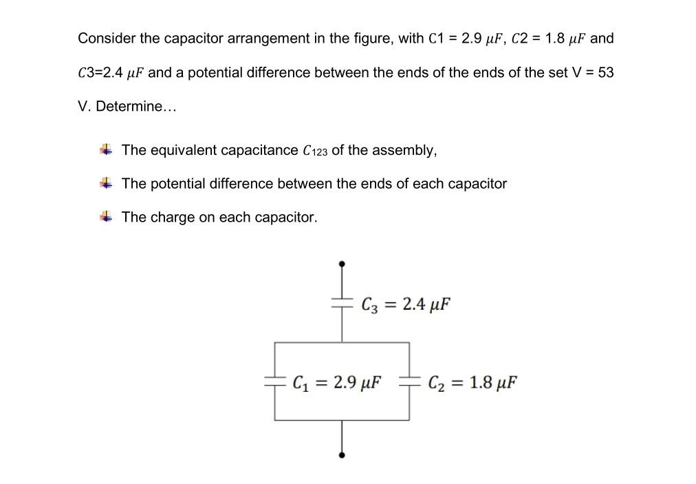
Consider the capacitor arrangement in the figure, with C1 = 2.9 MF, C2 = 1.8 uF and C3=2.4 °F and a potential difference between the ends of the ends of the set V = 53 V. Determine... + The equivalent capacitance C123 of the assembly, + The potential difference between the ends of each capacitor The charge on each capacitor. C3 = 2.4 uF = C1 = 2.9 uF C2 = 1.8 uF =