Page 1 of 1
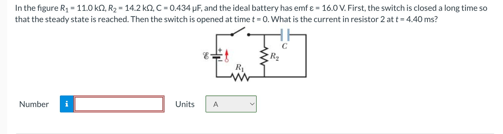
= In the figure R1 = 11.0 k12, R2 = 14.2 k12, C = 0.434 uF, and the ideal battery has emf ε = 16.0 V. First, the switch
Posted: Mon May 16, 2022 2:28 pm
by answerhappygod
- 1 (88.51 KiB) Viewed 53 times
= In the figure R1 = 11.0 k12, R2 = 14.2 k12, C = 0.434 uF, and the ideal battery has emf ε = 16.0 V. First, the switch is closed a long time so that the steady state is reached. Then the switch is opened at time t = 0. What is the current in resistor 2 at t = 4.40 ms? 8 С R2 R Number Units A