Page 1 of 1
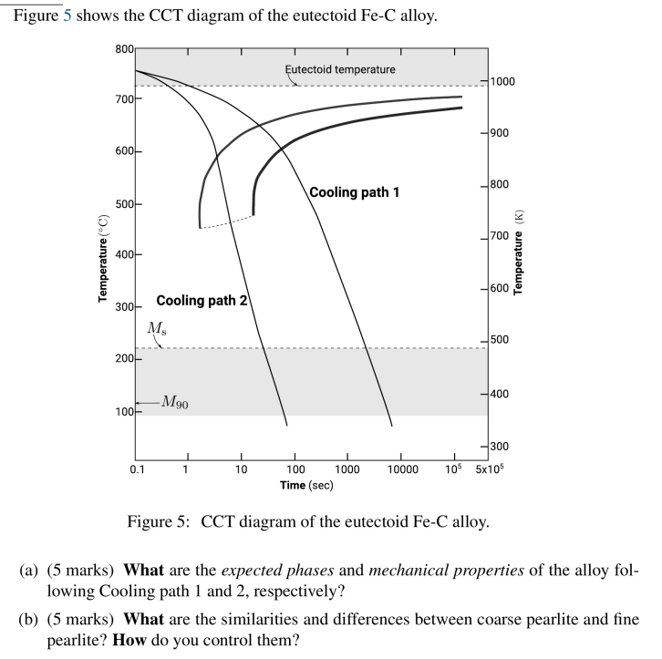
Figure 5 shows the CCT diagram of the eutectoid Fe-C alloy. 800 Eutectoid temperature 1000 7004 900 600+ 800 Cooling pat
Posted: Mon May 16, 2022 2:03 pm
by answerhappygod
- Figure 5 Shows The Cct Diagram Of The Eutectoid Fe C Alloy 800 Eutectoid Temperature 1000 7004 900 600 800 Cooling Pat 1 (106.59 KiB) Viewed 51 times
Figure 5 shows the CCT diagram of the eutectoid Fe-C alloy. 800 Eutectoid temperature 1000 7004 900 600+ 800 Cooling path 1 500 700 400 Temperature (°C) Temperature (K) 600 300F Cooling path 2 M 500 200 400 -M90 1001 300 0.1 I 10 1 10000 105 5x10⁵ 100 1000 Time (sec) Figure 5: CCT diagram of the eutectoid Fe-C alloy. (a) (5 marks) What are the expected phases and mechanical properties of the alloy fol- lowing Cooling path 1 and 2, respectively? (b) (5 marks) What are the similarities and differences between coarse pearlite and fine pearlite? How do you control them?