Page 1 of 1
Exercise 1 A MCM gas drive is depicted in the 1-D schematic below, where flow is left to right and G, and O. are composi
Posted: Mon May 16, 2022 1:29 pm
by answerhappygod
- Exercise 1 A Mcm Gas Drive Is Depicted In The 1 D Schematic Below Where Flow Is Left To Right And G And O Are Composi 1 (52.11 KiB) Viewed 58 times
- Exercise 1 A Mcm Gas Drive Is Depicted In The 1 D Schematic Below Where Flow Is Left To Right And G And O Are Composi 2 (27.19 KiB) Viewed 58 times
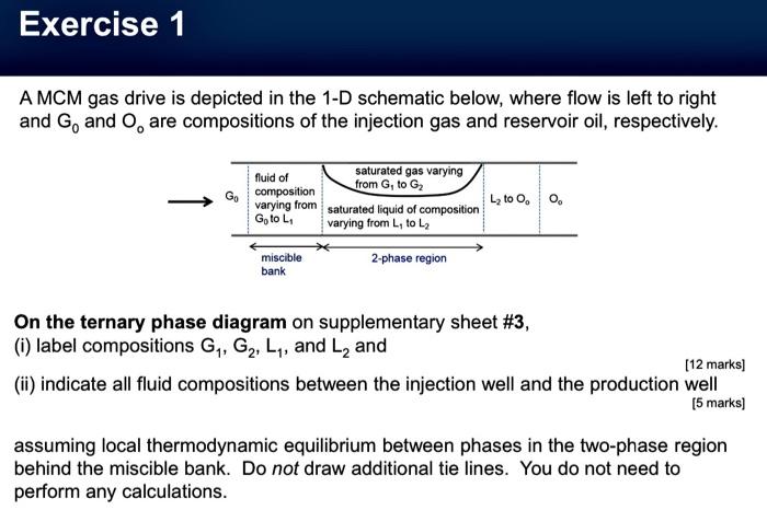
Exercise 1 A MCM gas drive is depicted in the 1-D schematic below, where flow is left to right and G, and O. are compositions of the injection gas and reservoir oil, respectively. saturated gas varying fluid of from G, to G composition varying from saturated liquid of composition GotoL varying from L, to L2 L2 to oo miscible bank 2-phase region On the ternary phase diagram on supplementary sheet #3, (i) label compositions G, G, L1, and L, and [12 marks] (ii) indicate all fluid compositions between the injection well and the production well (5 marks) assuming local thermodynamic equilibrium between phases in the two-phase region behind the miscible bank. Do not draw additional tie lines. You do not need to perform any calculations.
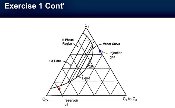
Exercise 1 Cont' C 2 Phase Region -Vapor Curve injection gas Tie Lines Liquid C7+ Cy to Ce reservoir oil