Page 1 of 1
Q4. (25%) A column shown in Fig. Q4 is braced against the horizontal load in both principal directions. The floor-to-flo
Posted: Mon May 16, 2022 12:00 pm
by answerhappygod
- Q4 25 A Column Shown In Fig Q4 Is Braced Against The Horizontal Load In Both Principal Directions The Floor To Flo 1 (43.73 KiB) Viewed 61 times
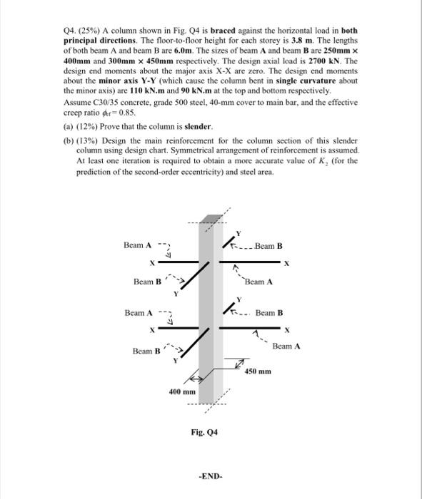
Q4. (25%) A column shown in Fig. Q4 is braced against the horizontal load in both principal directions. The floor-to-floor height for each storey is 3.8 m. The lengths of both beam A and beam B are 6.0m. The sizes of beam A and beam B are 250mm x 400mm and 300mm x 450mm respectively. The design axial load is 2700 KN. The design end moments about the major axis X-X are zero. The design end moments about the minor axis Y-Y (which cause the column bent in single curvature about the minor axis) are 110 kN.m and 90 kN.m at the top and bottom respectively. Assume C30/35 concrete, grade 500 steel, 40-mm cover to main bar, and the effective creep ratio &r=0.85 (a) (12%) Prove that the column is slender. (b) (13%) Design the main reinforcement for the column section of this slender column using design chart. Symmetrical arrangement of reinforcement is assumed. At least one iteration is required to obtain a more accurate value of K, (for the prediction of the second-order eccentricity) and steel area. Beam A ki Beam B Beam B Beam A Beam A Beam B Beam B Beam A 450 mm 400 mm Fig. 24 -END-